Electrical4yoou

In this website you will get all topics of Electrical Engineering and notes for competitive examination like SSCJE, DMRC , UPPCL , NTPC etc. This is 100% free website. You can easily find the topics which usually ask in University examination also.

Breaking

Monday, February 17, 2020

February 17, 2020

Open and Short Circuit Test of Transformer

Open and Short Circuit Test of Transformer


Open and short circuit tests are performed on a transformer to determine the:
  1. Equivalent circuit of transformer
  2. Voltage regulation of transformer
  3. Efficiency of transformer
The power required for open circuit tests and short circuit tests on a transformer is equal to the power loss occurring in the transformer.

Open Circuit Test on Transformer

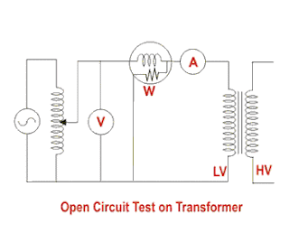
The connection diagram for open circuit test on transformer is shown in the figure. A voltmeter, wattmeter, and an ammeter are connected in LV side of the transformer as shown. The voltage at rated frequency is applied to that LV side with the help of a variac of variable ratio auto transformer.
The HV side of the transformer is kept open. Now with the help of variac, applied voltage gets slowly increased until the voltmeter gives reading equal to the rated voltage of the LV side. After reaching rated LV side voltage, we record all the three instruments reading (Voltmeter, Ammeter and Wattmeter readings).
The ammeter reading gives the no load current Ie. As no load current Ie is quite small compared to rated current of the transformer, the voltage drops due to this current that can be taken as negligible.
Since voltmeter reading V1 can be considered equal to the secondary induced voltage of the transformer, wattmeter reading indicates the input power during the test. As the transformer is open circuited, there is no output, hence the input power here consists of core losses in transformer and copper loss in transformer during no load condition. But as said earlier, the no-load current in the transformer is quite small compared to the full load current so, we can neglect the copper loss due to the no-load current. Hence, can take the wattmeter reading as equal to the core losses in the transformer.
Let us consider wattmeter reading is Po.
Where, Rm is shunt branch resistance of transformer.
If, Zm is shunt branch impedance of transformer.
Therefore, if shunt branch reactance of transformer is Xm,
These values are referred to the LV side of the transformer due to the tests being conducted on the LV side of transformer. These values could easily be referred to HV side by multiplying these values with square of transformation ratio.

Therefore it is seen that the open circuit test on transformer is used to determine core losses in transformer and parameters of the shunt branch of the equivalent circuit of the transformer.

Short Circuit Test on Transformer

The connection diagram for short circuit test on transformer is shown in the figure. A voltmeter, wattmeter, and an ammeter are connected in HV side of the transformer as shown. The voltage at rated frequency is applied to that HV side with the help of a variac of variable ratio auto transformer. We short-circuit the LV side of the transformer. Now with the help of variac applied voltage is slowly increased until the wattmeter, and an ammeter gives reading equal to the rated current of the HV side.
After reaching rated current of HV side, we record all the three instruments reading (Voltmeter, Ammeter and Watt-meter readings). The ammeter reading gives the primary equivalent of full load current IL. As the voltage applied for full load current in short circuit test on transformer is quite small compared to the rated primary voltage of the transformer, the core losses in transformer can be taken as negligible here.
Let’s say, voltmeter reading is Vsc. The watt-meter reading indicates the input power during the test. As we have short-circuited the transformer, there is no output; hence the input power here consists of copper losses in the transformer. Since the applied voltage Vsc is short circuit voltage in the transformer and hence it is quite small compared to the rated voltage, so, we can neglect the core loss due to the small applied voltage. Hence the wattmeter reading can be taken as equal to copper losses in the transformer. Let us consider wattmeter reading is Psc.
Where, Re is equivalent resistance of transformer.

If, Ze is equivalent impedance of transformer.
Therefore, if equivalent reactance of transformer is Xe.
These values are referred to the HV side of the transformer as the test is conducted on the HV side of the transformer. These values could easily be converted to the LV side by dividing these values with the square of transformation ratio.

Hence the short-circuit test of a transformer is used to determine copper losses in the transformer at full load. It is also used to obtain the parameters to approximate the equivalent circuit of a transformer.

Saturday, February 15, 2020

February 15, 2020

Different Types of Transformer Winding

Different Types of Transformer Winding


Core and Windings of Three Phase Core Type Transformer

There are different types of windings used for different kinds of applications and arrangements. Windings are the conductors wrapped in various forms like helical, disc, cylindrical, crossover which generates mmf that is carried by the core to other windings for having the different level of voltages. Mainly there are two types of transformer:
  1. Core type transformer
  2. Shell type transformer
In core type, we wrap the primary, and the secondary winding on the outside limbs and in shell type we place the primary and secondary windings on the inner limbs.
We use concentric type windings in core type transformer. We place low voltage winding near to the core. However, to reduce leakage reactance, windings can be interlaced. Winding for core type depends on many factors like current rating, short circuit withstand capacity, limit of temperature rise, impedance, surge voltage, transport facilities, etc.

Types of Winding used for Core Type Transformer

Cylindrical Windings

These windings are layered type and uses rectangular or round conductor shown in Fig.(a) and (b). The conductors are wound on flat sides shown in Fig.(c) and wound on the rib side in Fig.(d).

Uses of Cylindrical Windings

Cylindrical windings are low voltage windings used up to 6.6 kV for kVA up to 600-750, and current rating between 10 to 600 A.

 We often use cylindrical windings in its multi-layer forms. We use rectangular conductors in two-layered type because it is easy to secure the lead-out ends. Oil ducts separate the layers of the windings this arrangement facilitates the cooling through oil circulation in the winding.

 In multi-layered cylindrical windings, we use circular conductors, wound on vertical strips to improve cooling conditions. The arrangement creates oil ducts to facilitate better cooling. We use this types of winding for high voltage ratings up to 33 kV, 800 kVA and current ratings up to 80 A. The maximum diameter we use for a bare conductor is 4 mm.

Helical Windings

We use helical windings low voltage, high capacity transformers, where current is higher, at the same time windings turns are lesser. The output of transformer varies from 160 – 1000 kVA from 0.23-15 kV. To secure adequate mechanical strength the cross-sectional area of the strip not made less than 75-100 mm square. The maximum number of strips used in parallel to make up a conductor is 16.
There are three types:
  • Single Helical Winding
  • Double Helical Winding
  • Disc-Helical Winding
Single Helical Windings consist of winding in an axial direction along a screw line with an inclination. There is only one layer of turns in each winding. The advantage of Double Helical Winding is that it reduces eddy current loss in conductors. This is on account of the reduced number of parallel conductors situated in the radial direction.
In Disc-Helical Windings, the parallel connected strips are placed side by side in a radial direction to occupy total radial depth of winding.

Multi-layer Helical Winding


We use it commonly for high voltage ratings for 110 kV and above. These types of winding consist of several cylindrical layers concentrically wound and connected in series.
We make the outer layers shorter than inner layers to distribute capacitance uniformly. These windings primarily improve the surge behaviour of transformers.

Crossover Winding

We use these windings for high voltage windings of small transformers. The conductors are paper covered round wires or strips. The windings are divided into a number of coils in order to reduce voltage between adjacent layers. These coils are axially separated by a distance of 0.5 to 1 mm. The voltages between adjacent coils should not be more than 800 to 1000 V.
The inside end of a coil is connected to the output side end of the adjacent one as shown in above figure.The actual axial length of each coil is about 50 mm while the spacing between two coils is about 6 mm to accommodate blocks of insulating material. The width of the coil is 25 to 50 mm. The crossover winding has a higher strength than cylindrical winding under normal condition. However, the crossover has lover impulse strength than the cylindrical one. This type also consumes more labour cost.

Disc and Continuous Disc Winding

Primarily used for a high capacity transformer. The winding consist of a number of flat coils or discs in series or parallel. The coils are formed with rectangular strips wound spirally from the centre outwards in the radial direction as shown in the figure below.
The conductors can be a single strip or multiple strips in a parallel wound on the flat side. This makes robust construction for this type of windings. Discs are separated from each other with press-board sectors attached to vertical strips. The vertical and horizontal spacers provide radial and axial ducts for free circulation of oil which comes in contact with every turn. The area of the conductor varies from 4 to 50 mm square and limits for current are 12 – 600 A. The minimum width of oil duct is 6 mm for 35 kV. The advantage of the disc and continuous windings is their greater mechanical axial strength and cheapness.

Windings for Shell Type Transformer

Sandwich Type Winding

Allow easy control over the reactance the nearer two coils are together on
the same magnetic axis, the greater is the proportion of mutual flux and the less is the leakage flux. Leakage can be reduced by subdividing the low and high voltages sections. The end low voltages sections contain half the turns of the normal low voltage sections called half coils.
In order to balance the magnetomotive forces of adjacent sections, each normal section whether high or low voltage carries the same number of ampere-turns. The higher the degree of subdivision, the smaller is the reactance.

Advantages of Shell Type Windings in Transformers

  • High short-circuit withstand capability
  • High mechanical strength
  • High dielectric strength
  • Excellent control of leakage magnetic flux
  • Efficient cooling capability
  • Flexible design
  • Compact size.
  • Highly Reliable Design

February 15, 2020

Silica Gel Breather of Transformer

Silica Gel Breather of Transformer


Silica Gel Breather of Transformer

Whenever an electrical power transformer is loaded, the temperature of the transformer insulating oil increases, consequently the volume of the oil is increased. As the volume of the oil is increased, the air above the oil level in conservator will come out. Again at low oil temperature; the volume of the oil is decreased, which causes the volume of the oil to be decreased which again causes air to enter into conservator tank.
The natural air always consists of more or less moisture in it and this moisture can be mixed up with oil if it is allowed to enter into the transformer. The air moisture should be resisted during entering of the air into the transformer, because moisture is very harmful for transformer insulation. A silica gel breather is the most commonly used way of filtering air from moisture.
Silica gel breather for transformer is connected with conservator tank by means of breathing pipe.

Construction of Silica Gel Breather

The silica gel breather of transformer is very simple in the aspect of design. It is nothing but a pot of silica gel through which, air passes during breathing of transformer. The silica gel is a very good absorber of moisture. Freshly regenerated gel is very efficient, it may dry down air to a dew point of below -40oC. A well maintained silica gel breather will generally operate with a dew point of -35oC as long as a large enough quantity of gel has been used. The picture shows a silica gel breather of transformer.

Working Principle of Silica Gel Breather

Silica gel crystal has tremendous capacity of absorbing moisture. When air passes through these crystals in the breather; the moisture of the air is absorbed by them. Therefore, the air reaches to the conservator is quite dry, the dust particles in the air get trapped by the oil in the oil seal cup. The oil in the oil sealing cup acts as barrier between silica gel crystal and air when there is no flow of air through silica gel breather. The color of silica gel crystal is dark blue but, when it absorbs moisture; it becomes pink.
When there is sufficient difference between the air inside the conservator and the outside air, the oil level in two components of the oil seal changes until the lower oil level just reaches the rim of the inverted cup, the air then moves from high pressure compartment to the low pressure compartment of the oil seal. Both of these happen when the oil acts as core filter and removes the dust from the outside air.

Thursday, February 13, 2020

February 13, 2020

Transformer Testing | Type Tests and Routine Tests of Transformer

Transformer Testing | Type Tests and Routine Tests of Transformer


For confirming the specifications and performances of an electrical power transformer it has to go through a number of testing procedures. Some tests are done at a transformer manufacturer premises before delivering the transformer.
Transformer manufacturers perform two main types of transformer testingtype test of transformer and routine test of transformer.
Some transformer tests are also carried out at the consumer site before commissioning and also periodically in regular and emergency basis throughout its service life.

Type of Transformer Testing

Tests done at factory
  1. Type tests
  2. Routine tests
  3. Special tests
Tests done at site
  1. Pre-commissioning tests
  2. Periodic/condition monitoring tests
  3. Emergency tests

Type Test of Transformer

To prove that the transformer meets customer’s specifications and design expectations, the transformer has to go through different testing procedures in manufacturer premises. Some transformer tests are carried out for confirming the basic design expectation of that transformer. These tests are done mainly in a prototype unit not in all manufactured units in a lot. Type test of transformer confirms main and basic design criteria of a production lot.

Routine Tests of Transformer

Routine tests of transformer is mainly for confirming the operational performance of the individual unit in a production lot. Routine tests are carried out on every unit manufactured.

Special Tests of Transformer

Special tests of transformer is done as per customer requirement to obtain information useful to the user during operation or maintenance of the transformer.

Pre Commissioning Test of Transformer

In addition to these, the transformer also goes through some other tests, performed on it, before actual commissioning of the transformer at the site. The transformer testing performed before commissioning the transformer at the site is called the pre-commissioning test of transformer. These tests are done to assess the condition of transformer after installation and compare the test results of all the low voltage tests with the factory test reports.
Type tests of transformer include:
  1. Winding resistance test of transformer
  2. Transformer ratio test
  3. Transformer vector group test
  4. Measurement of impedance voltage/short circuit impedance (principal tap) and load loss (Short circuit test)
  5. Measurement of no-load loss and current (Open circuit test)
  6. Measurement of insulation resistance
  7. Dielectric tests of transformer
  8. Temperature rise test of transformer
  9. Tests on on-load tap-changer
  10. Vacuum tests on tank and radiators
Routine tests of transformer include
  1. Winding resistance test of transformer
  2. Transformer ratio test
  3. Transformer vector group test
  4. Measurement of impedance voltage/short circuit impedance (principal tap) and load loss (Short circuit test)
  5. Measurement of no load loss and current (Open circuit test)
  6. Measurement of insulation resistance
  7. Dielectric tests of transformer.
  8. Tests on on-load tap-changer.
  9. Oil pressure test on transformer to check against leakages past joints and gaskets
That means Routine tests of transformer include all the type tests except temperature rise and vacuum tests. The oil pressure test on transformer to check against leakages past joints and gaskets is included.
Special Tests of transformer include
  1. Dielectric tests.
  2. Measurement of zero-sequence impedance of three-phase transformers
  3. Short-circuit test
  4. Measurement of acoustic noise level
  5. Measurement of the harmonics of the no-load current.
  6. Measurement of the power taken by the fans and oil pumps.
  7. Tests on bought out components / accessories such as buchhloz relay, temperature indicators, pressure relief devices, oil preservation system etc.

Transformer Winding Resistance Measurement

Transformer winding resistance measurement is carried out to calculate the I2R losses and to calculate winding temperature at the end of a temperature rise test. It is carried out as a type test as well as routine test. It is also done at site to ensure healthiness of a transformer that is to check loose connections, broken strands of conductor, high contact resistance in tap changers, high voltage leads and bushings etc.
There are different methods for measuring of the transformer winding, likewise:
  • Current-voltage method of measurement of winding resistance.
  • Bridge method of measurement of winding resistance.
  • Kelvin bridge method of Measuring Winding Resistance.
  • Measuring winding resistance by Automatic Winding Resistance Measurement Kit.
Note: Transformer winding resistance measurement shall be carried out at each tap.

Transformer Ratio Test

The performance of a transformer largely depends upon perfection of specific turns or voltage ratio of transformer. So transformer ratio test is an essential type test of transformer. This test also performed as a routine test of transformer. So for ensuring proper performance of electrical power transformer, voltage and turn ratio test of transformer one of the important tests.
The procedure of the transformer ratio test is simple. We just apply three phase 415 V supply to HV winding, with keeping LV winding open. We measure the induced voltages at HV and LV terminals of the transformer to find out actual voltage ratio of the transformer. We repeat the test for all tap position separately.

Magnetic Balance Test of Transformer

Magnetic balance test of transformer is conducted only on three-phase transformers to check the imbalance in the magnetic circuit.

Procedure of Magnetic Balance Test of Transformer

  1. Keep the tap changer of transformer in normal position.
  2. Now disconnect the transformer neutral from ground.
  3. Then apply single phase 230 V AC supply across one of the HV winding terminals and neutral terminal.
  4. Measure the voltage in two other HV terminals in respect of neutral terminal.
  5. Repeat the test for each of the three phases.
In case of an autotransformer, a magnetic balance test of transformer should be repeated for LV winding also.
There are three limbs placed side by side in a core of the transformer. One phase winding is wound in one limb. The voltage induced in different phases depends upon the respective position of the limb in the core. The voltage induced in different phases of a transformer in respect to neutral terminals given in the table below.

Magnetizing Current Test of Transformer

Magnetizing current test of transformer is performed to locate defects in the magnetic core structure, shifting of windings, failure in between turn insulation or problem in tap changers. These conditions change the effective reluctance of the magnetic circuit, thus affecting the current required to establish flux in the core.
  1. Keep the tap changer in the lowest position and open all IV and LV terminals
  2. Then apply three phase 415 V supply on the line terminals for three-phase transformers and single phase 230 V supply on single phase transformers
  3. Measure the supply voltage and current in each phase
  4. Now repeat the magnetizing current test of transformer test with keeping tap changer in normal position
  5. Repeat the test while keeping the tap at highest position
Normally, there are two similar higher readings on two outer limb phases on transformer core and one lower reading on the center limb phase, in the case of three phase transformers.
An agreement to within 30% of the measured exciting current with the previous test is usually considered satisfactory. If the measured exciting current value is 50 times higher than the value measured during factory test, there is a likelihood of a fault in the winding which needs further analysis.
Caution: This magnetizing current test of a transformer is to be carried out before DC resistance measurement.

Vector Group Test of Transformer

In a 3 phase transformer, it is essential to carry out a vector group test of transformer. Proper vector grouping in a transformer is an essential criteria for parallel operation of transformers.
There are several internal connections of three-phase transformer are available on the market. These several connections give various magnitudes and phase of the secondary voltage; the magnitude can be adjusted for parallel operation by suitable choice of turn ratio, but the phase divergence cannot be compensated.
So we have to choose a transformer suitable for parallel operation whose phase sequence and phase divergence are same. All the transformers with the same vector ground have same phase sequence and phase divergence between primary and secondary.
Before procuring an electrical power transformer, you should ensure the vector group of the transformer, whether it will be matched with his or her existing system or not. The vector group test of transformer confirms his or her requirements.

Insulation Resistance Test or Megger Test of Transformer

Insulation resistance test of transformer is essential type test. This test is carried out to ensure the healthiness of the overall insulation system of an electrical power transformer.

Procedure of Insulation Resistance Test of Transformer

  1. Disconnect all the line and neutral terminals of the transformer
  2. Megger leads to be connected to LV and HV bushing studs to measure insulation resistance IR value in between the LV and HV windings
  3. Megger leads to be connected to HV bushing studs and transformer tank earth point to measure insulation resistance IR value in between the HV windings and earth
  4. Megger leads to be connected to LV bushing studs and transformer tank earth point to measure insulation resistance IR value in between the LV windings and earth
NB: It is unnecessary to perform insulation resistance test of transformer per phase wise in three-phase transformer. IR values are taken between the windings collectively as because all the windings on HV side are internally connected together to form either star or delta and also all the windings on LV side are internally connected together to form either star or delta.
Measurements are to be taken as follows:
  • For autotransformer: HV-IV to LV, HV-IV to E, LV to E.
  • For two winding transformer: HV to LV, HV to E, LV to E.
  • Three winding transformers: HV to IV, HV to LV, IV to LV, HV to E, IV to E, LV to E.
  • Oil temperature should be noted at the time of insulation resistance test of the transformer, since the IR value of transformer insulating oil may vary with temperature.
  • IR values to be recorded at intervals of 15 seconds, 1 minute and 10 minutes.
  • With the duration of application of voltage, IR value increases. The increase in IR is an indication of dryness of insulation.
  • Absorption coefficient = 1 minute value/15 secs. value.
  • Polarization index = 10 minutes value/1 minute value.

Dielectric Tests of Transformer

Dielectric test of a transformer is one kind of insulation test. This test is performed to ensure the expected overall insulation strength of the transformer. There are several tests performed to ensure the required quality of transformer insulation; the dielectric test is one of them. Dielectric test of the transformer is performed in two different steps.
First one is called Separate Source Voltage Withstand Test of transformer, where a single phase power frequency voltage of prescribed level, is applied on transformer winding under test for 60 seconds while the other windings and tank are connected to the earth, and it is observed that whether any failure of insulation occurs or not during the test.
The second one is the induced voltage test of Transformer where, three-phase voltage, twice of rated secondary voltage is applied to the secondary winding for 60 seconds by keeping the primary of the transformer open circuited.
The frequency of the applied voltage should be double of power frequency too. Here also if no failure of insulation, the test is successful.
In addition to dielectric tests of transformers, there are other types of test for checking insulation of transformer, such as lightning impulse test, switching impulse test and partial discharge test.

Induced Voltage Test of Transformer

The induced voltage test of the transformer is intended to check the inter-turn and line end insulation as well as main insulation to earth and between windings-
  1. Keep the primary winding of transformer open circuited.
  2. Apply three-phase voltage to the secondary winding. The applied voltage should be twice of the rated voltage of secondary winding in magnitude and frequency.
  3. The duration of the test shall be 60 seconds.
  4. The test shall start with a voltage lower than 1/3 the full test voltage, and it shall be quickly increased up to the desired value.
The test is successful if no breakdown occurs at full test voltage during the test.

Temperature Rise Test of Transformer

Temperature rise test of transformer is included in type test of transformer. In this test, we check whether the temperature-rising limit of the transformer winding and oil as per specification or not. In this type test of the transformer, we have to check oil temperature rise as well as winding temperature rise limits of an electrical transformer.

February 13, 2020

Efficiency of Transformer

Efficiency of Transformer


Introduction of Efficiency of Transformer

Transformers form the most important link between supply systems and load. Transformer’s efficiency directly affects its performance and aging. The transformer’s efficiency, in general, is in the range of 95 – 99 %. For large power transformers with very low losses, the efficiency can be as high as 99.7%. The input and output measurements of a transformer are not done under loaded conditions as the wattmeter readings inevitably suffer errors of 1 – 2%. So for the purpose of efficiency calculations, OC and SC tests are used to calculate rated core and winding losses in the transformer. The core losses depend on the transformer rated voltage, and the copper losses depend on the currents through the transformer primary and secondary windings. Hence transformer efficiency is of prime importance to operate it under constant voltage and frequency conditions. The rise in the temperature of the transformer due to heat generated affects the life of transformer oil properties and decides the type of cooling method adopted. The temperature rise limits the rating of the equipment. The efficiency of transformer is simply given as:
  • The output power is the product of the fraction of the rated loading (volt-ampere), and power factor of the load
  • The losses are the sum of copper losses in the windings + the iron loss + dielectric loss + stray load loss.
  • The iron losses include the hysteresis and eddy current losses in the transformer. These losses depend on the flux density inside the core. Mathematically,
    Hysteresis Loss :
    E
  • EddyCurrent Loss :

  • Where kh and ke are constants, Bmax is the peak magnetic field density, f is the source frequency, and t is the thickness of the core. The power ‘n’ in the hysteresis loss is known as Steinmetz constant whose value can be nearly 2.
  • The dielectric losses take place inside the transformer oil. For low voltage transformers, it can be neglected.
  • The leakage flux links to the metal frame, tank,etc. to produce eddy currents and are present all around the transformer hence called stray loss, and it depends on the load current and so named as ‘stray load loss.’ It can be represented by resistance in series to the leakage reactance.

Efficiency Calculation of the Transformer

The equivalent circuit of transformer referred to primary side is shown below. Here Rc accounts for core losses. Using Short circuit(SC) test, we can find the equivalent resistance accounting for copper losses as
Let us define x% be the percentage of full or rated load ‘S’ (VA) and let Pcufl(watts) be the full load copper loss and cosθ be the power factor of the load. Also, we defined Pi (watts) as core loss. As copper and iron losses are major losses in the transformer hence only these two types of losses are taken into account while calculating efficiency. Then the efficiency of transformer can be written as :
Where, x2Pcufl = copper loss(Pcu) at any loading x% of full load.
The maximum efficiency (ηmax) occurs when the variable losses equal to the constant losses. Since the copper loss is load dependent, hence it is a variable loss quantity. And the core loss is taken to be the constant quantity. So the condition for maximum efficiency is :

Now we can write maximum efficiency as :
This shows that we can obtain maximum efficiency at full load by proper selection of constant and variable losses. However, it is difficult to obtain maximum efficiency as copper losses are much higher than the fixed core losses.
The variation of efficiency with loading can be represented by figure below :

All Day Efficiency of Transformer


It is an energy-based efficiency calculated for distribution transformers. Unlike power transformer which is switched in or out depending on the load handled by it, a distribution transformer loading continuously fluctuates for 24 hours a day. As core losses are independent of load, the all-day efficiency depends on the copper losses.We define it as the ratio of output energy delivered to input energy for a 24 hour cycle. High energy efficiencies are achieved by restricting core flux densities to lower values (as the core losses are dependent on flux density) by using relatively larger cross-section or larger iron/copper weight ratio.